10+ lead/lag pump control wiring diagram
Simplex sump pump control panel wiring diagram from. If using single action switches with a control panel please.

Variable Speed Pump Instalation Text Plcs Net Interactive Q A
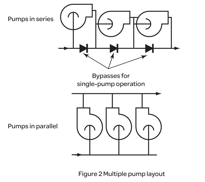
Wiring and Piping Diagrams 8 2-Pump 1-Call 1-Flow 8 2-Pump 1-Call 2-Flow 10 3-Pump 1-Call 1-Flow 12.

. Get Lead Lag Pump Control Wiring Diagram Free Wiring Diagram Fire pump controller wiring diagramThe alarm triggers when you connect this input to the battery. Be sure to follow connection diagram as lead and lag pressure switch must. Welcome To Electric Wiring Schooltoday We Learn Submersible Pump Control Box Wiring Diagrama Submersible Pump Pushes Water To The Surface By Converting Rot.
PRODUCTS 201 GENERAL A. Jul 13 2018 Name. 163D162 Myvi Power Window Wiring Diagram.
A wiring diagram is a simplified traditional. Another advantage of the four-float system is the ability to create a storage difference between the lag float and the alarm float. 130F63E Ngk Lamp Timer 12v Dc Wire Diagram.
The Control Panel shall be designed and built as integrated pre-wired equipment. The Design Is Constructed Around A Single Ic 4049 Whose 6 Not. Originally Posted by XcelTech.
The wiring diagrams illustrated in this installation manual represent a sampling of the many ways the iO-LL can be applied for leadlag control. 14EC032 Mazda 3 Fuse Box Diagram. Tighten screws on terminal block.
OvervIeW OF THe OPeraTIng MODes The PLL control is a Lead-Lag Pump control. This relay will alternate two compressors and provide a leadlag function with two pressure switches. Wiring diagram pump lead lag control boiler belimo multiple water hydronic systems low sr lf24 cut safgard sample fire system How To.
Use Relays In Your Wiring Projects. I am trying to talk my boss into understand the simple yet very effective strategy behind how I wire leadlag pumps. A wiring diagram is a simplified standard pictorial depiction of an electrical circuit.
If the water level rises fs 2 will close first but the motor will not start. Leadlag pump control wiring diagram Sabtu 22 Oktober 2022 This relay will alternate two compressors and provide a leadlag function with two pressure switches. Lead lag pump control wiring diagram e way is to have the stand by pump pump 2 automatically e on when the lead pump pump 1 fails but pump 1 will always be the.
15E5BCB Mallory Ignition Systems Wiring Diagrams. Detailed external wiring diagram and sequence of operation. The level changes with the depth of the.
Sump pump control panel wiring diagram.

Vertical Multi Stage Booster

Semix Igbt Und Gleichrichter Modulfamilie Fur Lotfreie Montage Semikron
What Is An Example Of Applications That Use Plc In Various Industries Today How Does It Affect Their Daily Living Quora

Electrogage Pump Controller Eg Controls

Soft Actuator Materials For Electrically Driven Haptic Interfaces Ankit 2022 Advanced Intelligent Systems Wiley Online Library

Submersible Water Pump Control Panel Wiring Diagram Electrical Technologies Youtube

How To Program Lead Lag Pumping In Ignition Corso Systems
Pump Sequence Control Eurotherm By Schneider Electric

Submersible Pump Control Box Wiring Diagram For 3 Wire Single Phase Submersible Pump Submersible Electrical Circuit Diagram

Pdf Operation And Control Of P System Osman Khaleel Academia Edu
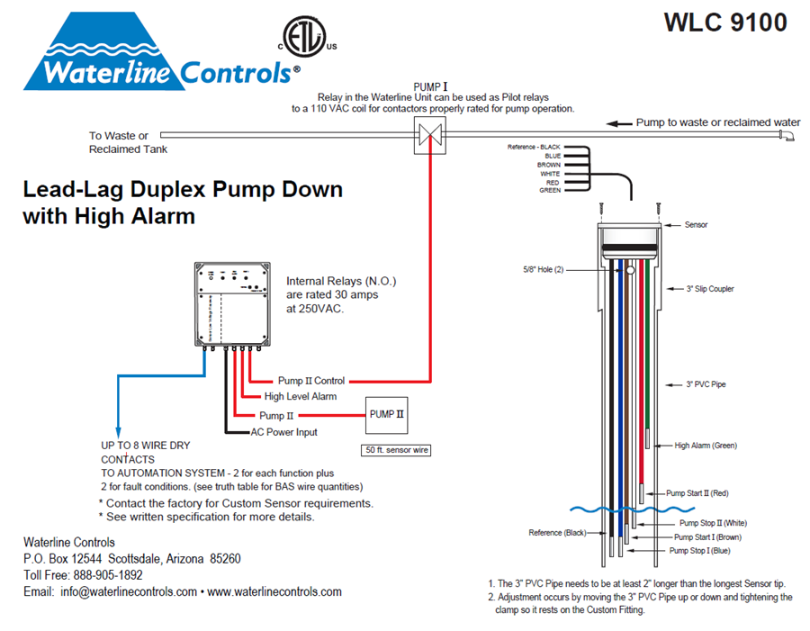
Wlc9100 Lead Lag Dual Pump Down Alt Pumps High Level
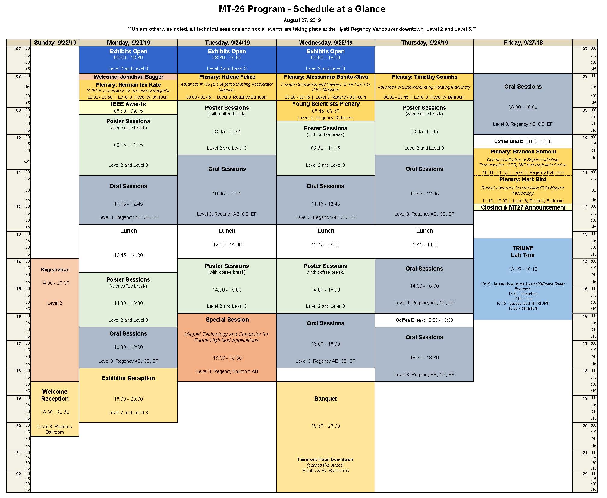
Mt26 Abstracts Timetable And Presentations 22 27 September 2019 Indico

Submersible Turbine Pumps Precision Pumping Systems
What Is An Example Of Applications That Use Plc In Various Industries Today How Does It Affect Their Daily Living Quora

Three Phase Duplex Alternating Pump M Tech Control
Gene Expression Variability Underlies Adaptive Resistance In Phenotypically Heterogeneous Bacterial Populations Acs Infectious Diseases
Lead Lag Pump Alternation Control Precision Digital